The purpose of the LAGR project
is to design vision and learning algorithms
to allow the robot to navigate in complex outdoors environment solely
from camera input.
Our team is one of 10 participants in the program funded by
DARPA.
The government periodically runs competitions between the teams.
The software from each team is loaded and run by the goverment team
on their robot.
The robot is given the GPS coordinates of a goal to which it must
drive as fast as possible. The terrain is unknown in advance.
The robot is run three times through the test course.
The software can use the knowledge acquired during the early
runs to improve the performance on the latter runs.
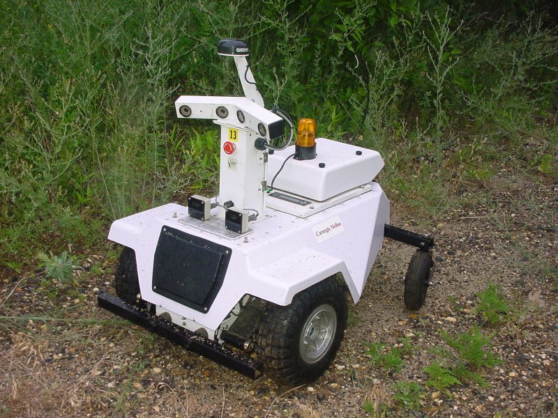
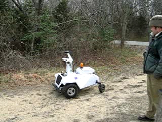
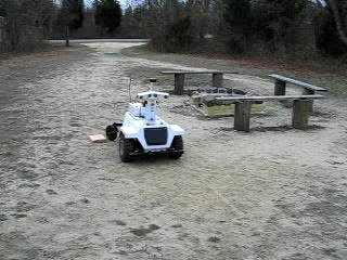
LAGR Robot #27 "Coureur".
Latest Video
Watch a video describing the final version of our system (version 4.0)
Raia Hadsell, Pierre Sermanet, Marco Scoffier, Ayse Erkan, Koray Kavackuoglu, Urs Muller and Yann LeCun: Learning Long-Range Vision for Autonomous Off-Road Driving, Journal of Field Robotics, 26(2):120-144, February 2009, \cite{hadsell-jfr-09}.
Pierre Sermanet, Raia Hadsell, Marco Scoffier, Matt Grimes, Jan Ben, Ayse Erkan, Chris Crudele, Urs Muller and Yann LeCun: A Multi-Range Architecture for Collision-Free Off-Road Robot Navigation, Journal of Field Robotics, 26(1):58-87, January 2009, \cite{sermanet-jfr-09}.
Pierre Sermanet, Marco Scoffier, Chris Crudele, Urs Muller and Yann LeCun: Learning Maneuver Dictionaries for Ground Robot Planning, Proc. 39th International Symposium on Robotics (ISR'08), 2008, \cite{sermanet-isr-08}.
Raia Hadsell, Ayse Erkan, Pierre Sermanet, Marco Scoffier, Urs Muller and Yann LeCun: Deep Belief Net Learning in a Long-Range Vision System for Autonomous Off-Road Driving, Proc. Intelligent Robots and Systems (IROS'08), 2008, \cite{hadsell-iros-08}.
Pierre Sermanet, Raia Hadsell, Marco Scoffier, Urs Muller and Yann LeCun: Mapping and Planning under Uncertainty in Mobile Robots with Long-Range Perception, Proc. Intelligent Robots and Systems (IROS'08), 2008, \cite{sermanet-iros-08}.
Ayse Erkan, Raia Hadsell, Pierre Sermanet, Jan Ben, Urs Muller and Yann LeCun: Adaptive Long Range Vision in Unstructured Terrain, Proc. Intelligent Robots and Systems (IROS'07), 2007, [key=erkan-iros-07].
Raia Hadsell, Ayse Erkan, Pierre Sermanet, Jan Ben, Koray Kavukcuoglu, Urs Muller and Yann LeCun: A Multi-Range Vision Strategy for Autonomous Offroad Navigation, Proc. Robotics and Applications (RA'07), 2007, [key=hadsell-ra-07].
Pierre Sermanet, Raia Hadsell, Jan Ben, Ayse Naz Erkan, Beat Flepp, Urs Muller and Yann LeCun: Speed-Range Dilemmas for Vision-Based Navigation in Unstructured Terrain, Proc. 6th IFAC Symposium on Intelligent Autonomous Vehicles, 2007, [key=sermanet-07].
Raia Hadsell, Pierre Sermanet, Ayse Erkan, Jan Ben, Jeff Han, Beat Flepp, Urs Muller and Yann LeCun: On-line Learning for Offroad Robots: Using Spatial Label Propagation to Learn Long-Range traversability, Proc. Robotics Science and Systems 07, 2007, [key=hadsell-rss-07].
Raia Hadsell, Pierre Sermanet, Jan Ben, Ause Erkan, Jeff Han, Matt Grimes, Sumit Chopra, Yury Sulsky, Beat Flepp, Urs Muller and Yann LeCun: On-line Learning for Offroad Robots: Using Spatial Label Propagation to Learn Long-Range traversability, Computational and Biological Learning Lab, Courant Institute, NYU, 2007, [key=hadsell-lagrtr-07].
The robot has two independently controled, electric-powered front
wheels and two caster wheels at the rear. The sensors are:
Two "bumblebee" 1024x768 color stereo camera pairs mounted on
the mast, providing a 110 degree field of view.
a 6-degree of freedom Inertial Measurement Units (IMU)
wheel encoders, and a GPS for pose estimation.
a front bumper with left and right switch sensors.
two short-range infrared sensors that can (unreliably)
detect obstacles up to 1.5 meters away.
In its original version, the robot contained three 1.4GHz Pentium-M
based computers running Linux in its belly, plus a 4th processor for
low-level control tasks. The new version has three dual-core 2.0GHz
Pentium-M. The computers are connected through a Gigabit ethernet
network. One computer is connected to the left camera pair, one to
the right camera pair, and one is for general use (called the
planner).
Communication with the outside world is provided through WiFi.
The Netscale/NYU software to run the robot is entirely implemented
in the Lush language, a dialect
of Lisp specifically designed for numerical taks, particularly
computer vision and machine learning.
Separate Lush processes running left eye and right eye computers
perform image acquisition, preprocessing, rectification, stereo,
short-range obstacle detection, and long-range obstacle detection with
on-line self learning. Each process sends a local map of the
environment to the planner computer through a socket. The planner
computer runs several Lush processes for combining the various
maps, planning a route, and driving the robot.
The Task: Vision-Based Navigation with Machine Learning
Robot navigation in outdoors environments solely from vision is a very
challenging problem.
The purpose of the LAGR project is to improve the state of the art in
vision-based outdoors robot navigation by using learning methods.
A typical test run of the LAGR robot consists in placing the robot in
an unknown terrain, and letting it drive autonomously to a prescribed
GPS location as fast as possible. The robot is run three times through
the course. Information can be gathered during during one run so as to
improve the performance on subsequent runs.
A typical course is 100 to 200 meters through various outdoors
environments with a variety of terrains (grass, dirt, sand, roads,
forest grounds), and natural and artificial obstacles (trees, bushes,
rocks, hay bales, fences,...).
The Problem: The Short-Sightedness of Stereo Vision
The method of choice for vision-based driving in off-road mobile
robots is to construct a traversibility map of the environment using
stereo vision. In the most common approach, a stereo matching
algorithm, applied to images from a pair of stereo cameras, produces a
"point-cloud", in which the visible pixels are given an XYZ position
relative to the robot. A traversibility map can then be derived using
various heuristics, such as counting the number of points that are
above the ground plane in a given map cell. Maps from multiple frames
are assembled in a global map in which path finding algorithms are
run.
One problem with real-time map building from stereo is that the
accuracy of range estimates degrades quickly above 7 to 10 meters.
This causes robots to be "short-sighted", or as if in a self-imposed
``fog''. The robot would often drive into dead-ends, and take
excessive time discovering pathways that, while beyond stereo range,
would be obvious to a human observer.
Top view of a map generated from stereo (stereo is run
at 320x240 resolution). The map is "smeared out" and sparse at long range
because range estimates from stereo become inaccurate above 8 to 10
meters. Traversibility maps built from this are either short range
or inaccurate. (click on image for high res version)
NSNYU System v4.0: Final Version
This system first became operational in November 2007.
Overview
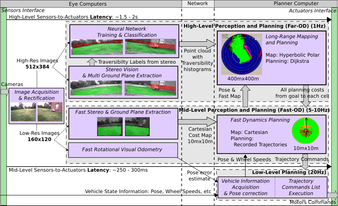
The system is composed of the following components:
Fast and short-range stereo-based obstacle detection module
(Fast-OD): this module runs as an independent thread at 5 to 10
frames per second and detects nearby obstacles within a 5 meter
radius.
Short-range planning and control system with learned
dynamics: this module uses the short-range map produced by fast
obstacle detector to plan initial segments of trajectories to a 2.5
meter radius. To take the robot dynamical constraints into account, a
set of possible inital trajectories is automatically learned (by
observing a human driver) and stored in a trajectory table. The best
trajectory is selected from the table using the map information.
Medium-range stereo-based obstacle detection system: this
module uses stereo vision, ground fitting (using multiple planes),
and various heuristics, to identify obstacles within 10 to 12
meters. Each pixel in the field of view is labeled as one of five
categories: super-traversable, traversable, obstacle foot line,
obstacle, super-obstacle. These labels are used to train the
convolutional net based long-range obstacle detector (Far-OD).
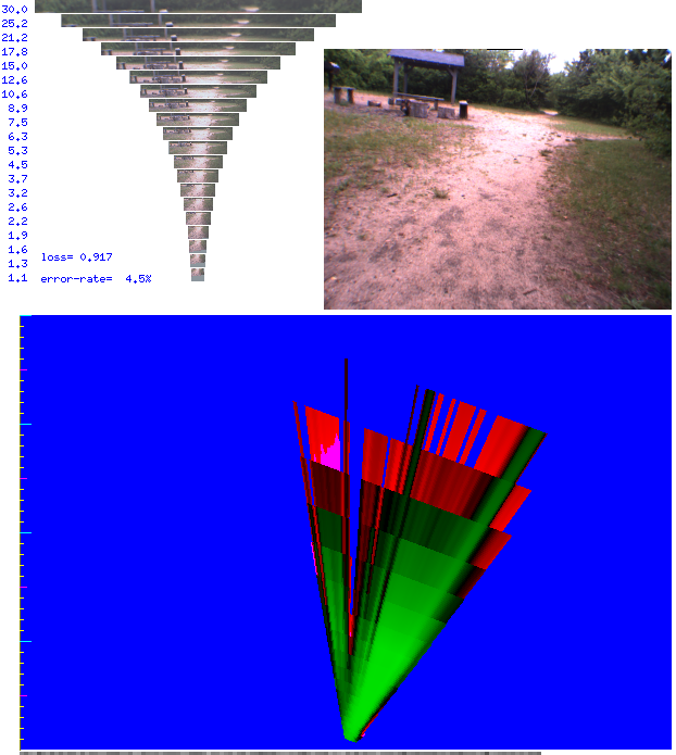
Horizon-leveling and image pyramid extraction: the
trainable long-range obstacle detection system (Far-OD) is fed with
raw pixel data, and trained with objects that are within 10 to 12
meters (in the range of the medium-range stereo labeler). Images of
objects in the world must be presented to the Far-OD in such a way
that their size in pixel is roughly independent of their distance
from the robot. This is achieved by using a horizon-leveled
multi-resolution image pyramid. Each band in the pyramid is scaled so
that any objects whose foot is likely to appear in that band will
have a constant height. For example, the band containing the portion
of the image in which the feet of objects that are 6 to 8 meters away
will be scaled down with twice the ratio of the band containing the
portion of the image in which the feet of objects are 12 to 16 meters
away.
Long-Range obstacle detection with convolutional network:
the convolutional network module is fed with the horizon-leveled
image bands from the pyramid and extract a 100-dimensional feature
vector for every 25x12 pixel window in the image bands. These feature
vectors are fed to a logistic regression classifier that is trained
on-line (as the robot runs) with labels produced by the medium-range
stereo module. Feature vectors from the last few frames are kept in a
short-term memory (a ring buffer) to train the classifier.
This module runs at about 1 frame per second.
Hyperbolic-Polar Map: labels from the various obstacle
detection systems are combined and accumulated into a hyperbolic
polar map centered on the robot. Although the radius of the map is
essentially infinite, its maximum usable range is 100 to 200
meters. Label information from multiple successive frames are
accumulated in category histograms stored at each map cell. Before
planning, the category histograms are transformed into traversability
costs. Planning a route to the goal map performed using a A* path
planning algorithm.
Low-cost visual odometry system: A high-efficiency, low-cost
visual odometry system constantly estimates the rotational speed of
the robot and accurately places the robot in its map. In the absence of this
module, estimates of the robot orientation are often inaccurate, due
to wheel slippage. As a result the map gets blurry and the planning
gets erratic.
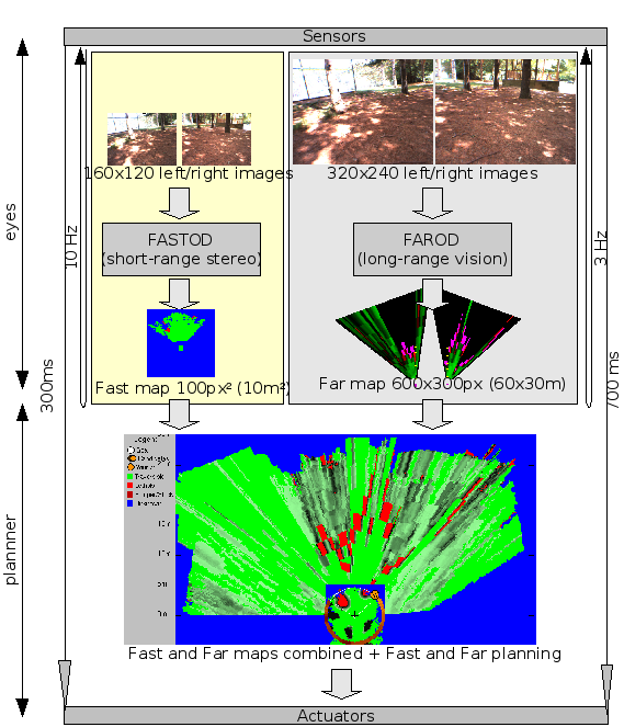
System architecture.
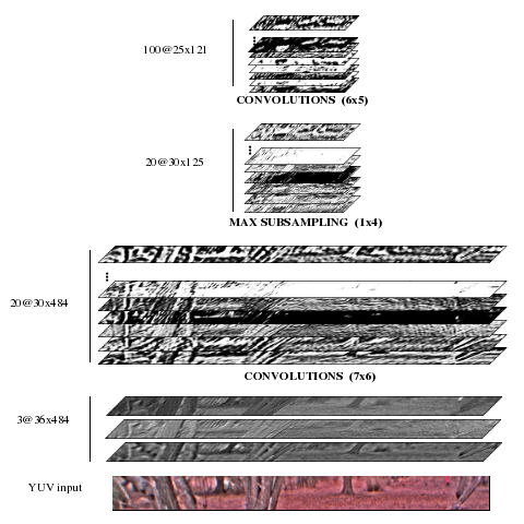
Convolutional Network
Convolutional networks are trainable machines composed of multiple
layers of trainable non-linear convolutional filters. Convolutional
networks have been used with great success (and deployed commercially)
for such applications as handwriting recognition (e.g. check reading),
face and people detection in images, and such.
The main advantage of convolutional networks is that they can be fed
with "raw" pixels, without requiring extensive
hand-crafted. pre-processing. The training process in convolutional
nets automatically produces relevant features. In this system, the
convolutional network is fed with the horizon-leveled image bands from
the multiscale image pyramid.
The convolutional net can be seen as extracting a 100-dimensional
feature vector for every 25x12 pixel window in the image bands (the
windows are stepped every 4 pixels horizontally).
These feature vectors are fed to a logistic regression classifier that
is trained on-line (as the robot runs) using the labels produced by
the medium-range stereo module. Feature vectors from the last few
frames are kept in a short-term memory (a ring buffer) to train the
classifier. This module runs at about 1 frame per second.
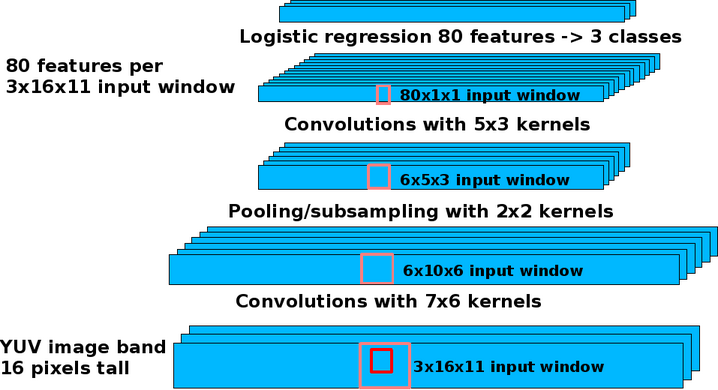
Convolutional network architecture for long-range obstacle detection.
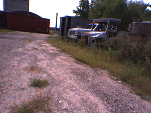
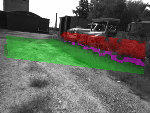
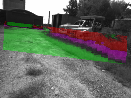
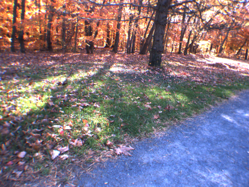
Results of Long-Range Obstacle Detection
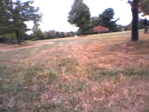
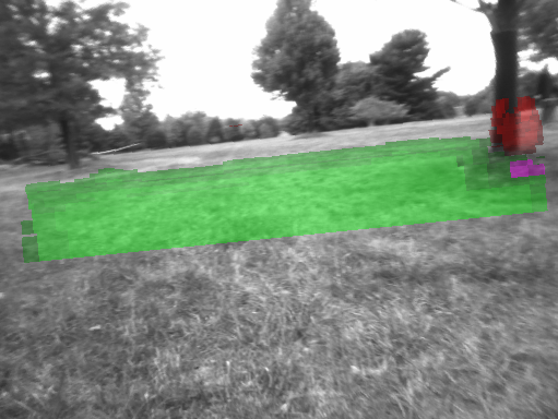
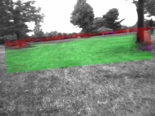
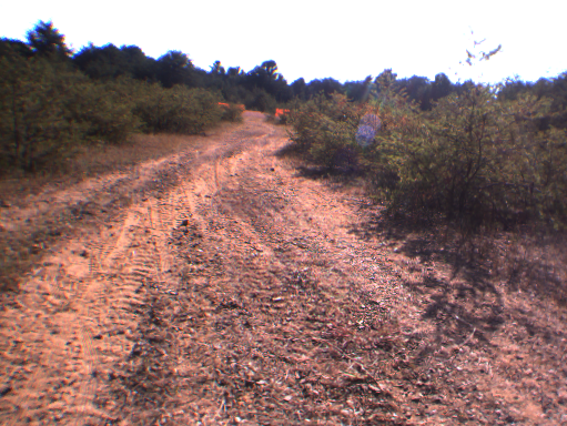
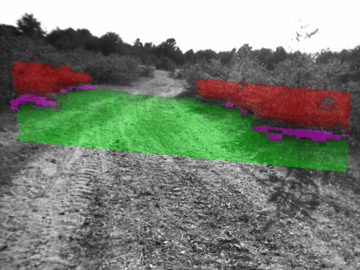
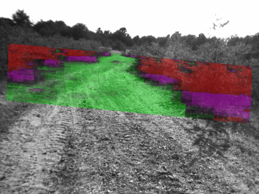
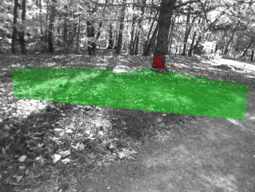
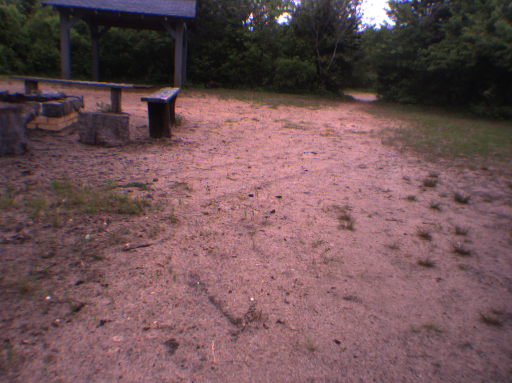
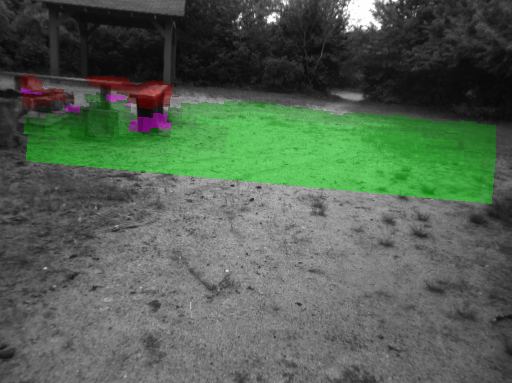
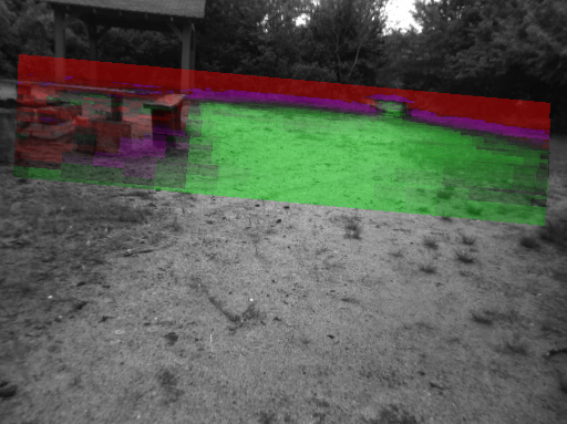
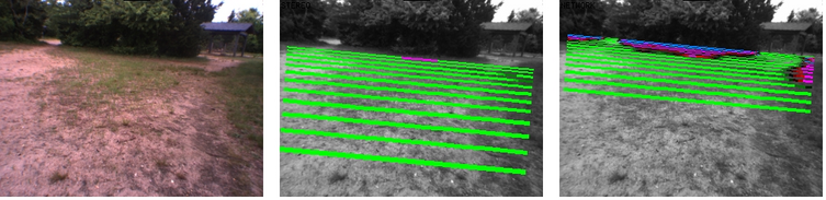
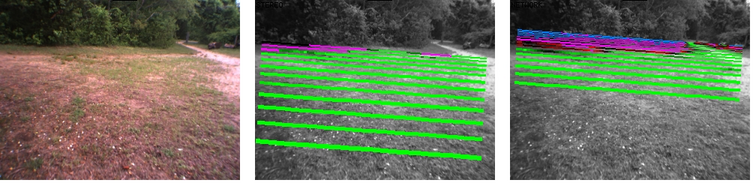
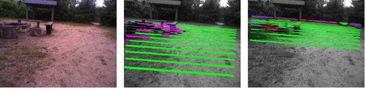
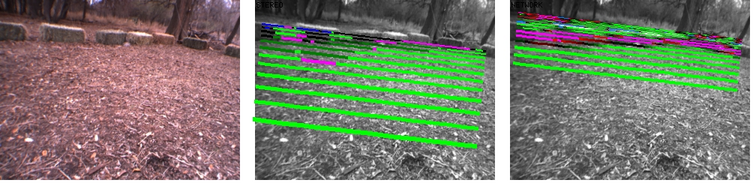
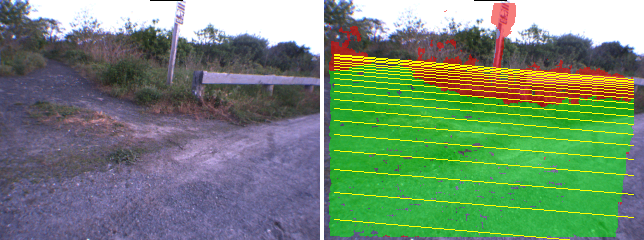
Below is a series of triplets of images showing the result of the
medium-range and long-range vision systems.
Each row shows three images:
left image: the original image as seen from one of the cameras.
middle image: labeling produced by the medium-range stereo labeling system.
right image: labeling produced by the convolutional net long-range vision system.
Green indicates a traversable area, purple indicates an obstacle footline,
and red indicates an obstacle.
Results of long-range obstacle detection
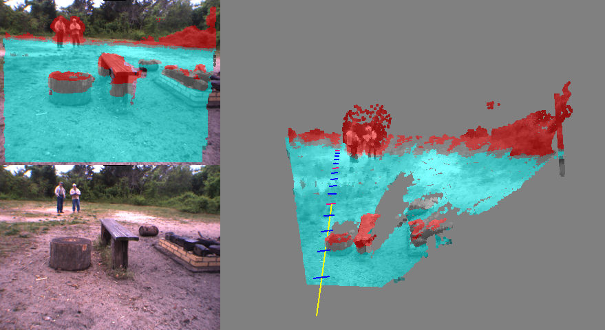
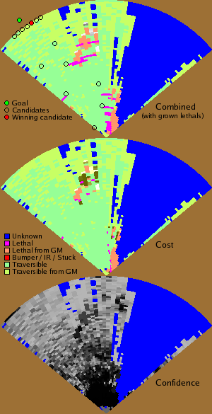
Hyperbolic Polar Map
The results from the various obstacle labeling systems are combined
and accumulated into a map of the surroundings of the robot.
The map is a hyperbolic-polar map centered on the robot. In a
hyperbolic representation, the entire world is mapped to a
finite-radius disk using a hyperbolic mapping. Label information from
multiple successive frames are accumulated in category histograms
stored at each map cell. Before planning, the category histograms are
transformed into traversability costs. Planning a route to the goal
map performed using a A* path planning algorithm.
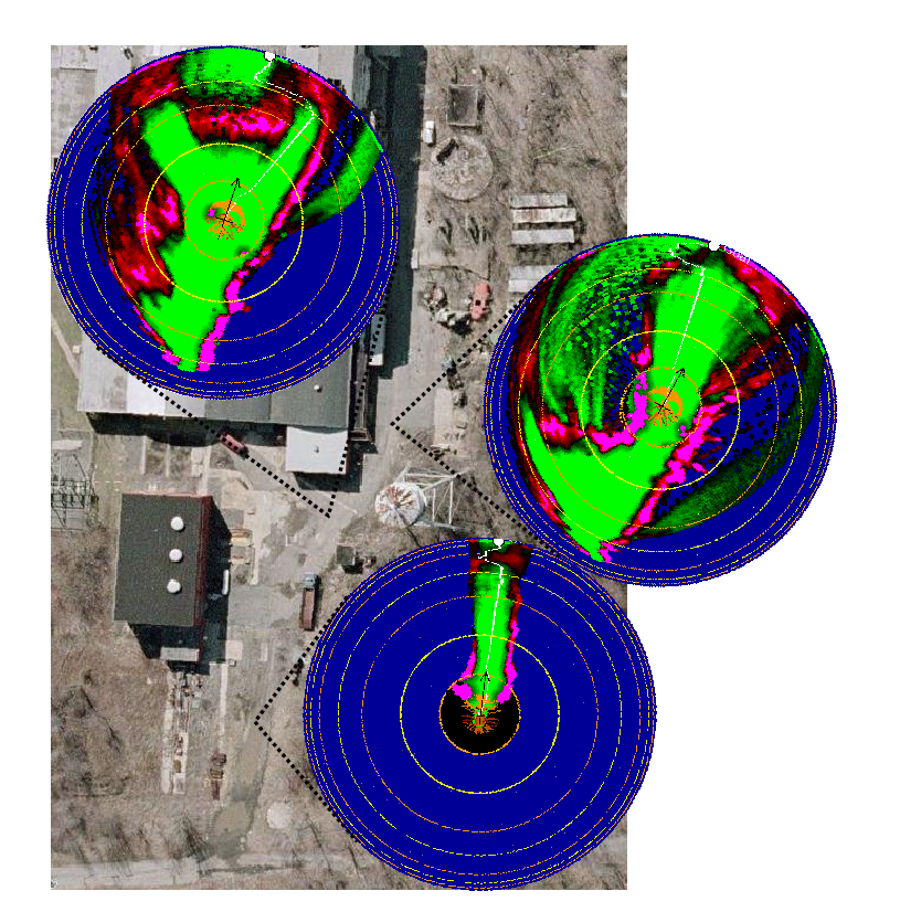
The picture below shows examples of map produced at various points
along a trajectory followed by the robot.
Example of maps produced by the perception system.
NSNYU System v3.0: Fast OD - Far OD - Convolutional Net
This system was operational between Winter 2007 and Summer 2007.
While it worked satisfactorily, it was found to be too sensitive
to the ground plane assumption.
The v2.0 system had a major flaw: the long-range obstacle detector
took too long to run, and created long latencies (sometimes as long as
1/2 second) in the visual control loop. These delays, combined with
built-in delays in the low-level control loop of the robot firmware,
caused the robot to crash into obstacles before having time to avoid
them.
We designed a new system composed of a very fast, very short range,
stereo-based obstacle avoidance system (FastOD), combined with
a slower, learning-based, long-range obstacle detection system
(FarOD).
FastOD operates on 160x120 resolution images, is purely based on stereo,
produces a map with 5 meter radius, and runs at 10 frames per second.
FarOD uperates on 320x240 resolution images, combines stereo and a
trainable obstacle detector based on convolutional nets, produces a
map with 35 meter radius, and runs at 3 frames per second.
The FastOD had a range of 5 meters, while the FarOD had a range of 35 meters.
The RBF-based long-range obstacle detector of v2.0 was replaced by
new architecture based on the convolutional network method.
The convolutional network obstacle detector operates on the
size-normalized bands from the pyramid. It has 4 layers and operates
on YUV components (with contrast normalization on the Y
component). The network is first trained off-line on log files. Each
column of pixel in the bands that are withing stereo range are
assigned a traversibility label by the stereo vision system. The
convolutional net is trained map each band to this corresponding row
of stereo labels.
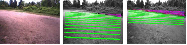
The long-range obstacle detector works very well, as shown
in the pictures below. Each panel shows (from left to right)
the original image, the traversibility labels produced by
stereo (up to 10-12 meters), and the traversibility labels
produced by the convolutional net long-range obstacle detector
trained on-line (up to 30-35 meters).
The v3.0 system worked quite well, but the distance estimated it
provided were very dependent on the ground plane assumption.
Furthermore, there were various issues with the robot-centered
cartesian map populated by the long-range obstacle detector
(FarOD). First, it was prohibitively expensive to extend this map
beyond the range of 40 meters or so (the cartesian map would become
prohibitively large). Second, the map was very "blurry" in the far
range because range estimates vary considerably from one frame to the
next. Obstacles estimated to be at 25 meters in one frame could very
well be placed at 35 meters in the next frame.
Hence, we decided to implement a robot-centered map for FarOD
whose cell shape would somewhat reflect the distance uncertainties
produced by FarOD.
This resulted in the so-called Hyperbolic-Polar Map, or
H-Polar Map for short.
NSNYU System v2.0: Long-Range Map with On-Line Learning
This version was operational between summer 2006 and winter 2006.
The long-range obstacle detection system with on-line learning worked very well.
The overall system worked OK, but never quite fulfilled our expectations.
The main reason was excessive latency in the control loop.
Humans can easily locate pathways from monocular views, e.g. trails in
a forest, holes in a row of bushes. Our second system represents an
attempt to use on-line learning to provide the same capability to a
mobile robot. Although supervised learning can be used for robot
driving (see the Dave project),
autonomous learning is far preferable. One long-advocated idea for
autonomous learning in robots is to use the output of reliable modules
(such as traversibility from stereo at short range) to provide labels
for a trainable module (such as a long-range obstacle detector).
This has come to be known as "near to far learning".
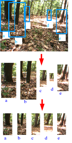
Our proposed approach, designed for the LAGR robot, builds a
distance-invariant pyramid of images at multiple scales, such
that the appearance in the image at scale X of an object sitting on
the ground X meters away is identical to the appearance in the image
of scale Y of the same object when sitting on the ground Y meters
away. The process is depicted at right. Windows are extracted from
the image. The size of a window is inversely proportional
to the estimated distance of the foot of obstacles that
fall in the bottom third of the window (the distance is
estimated through a ground plane fitting). The windows
are then normalized to a fixed height.
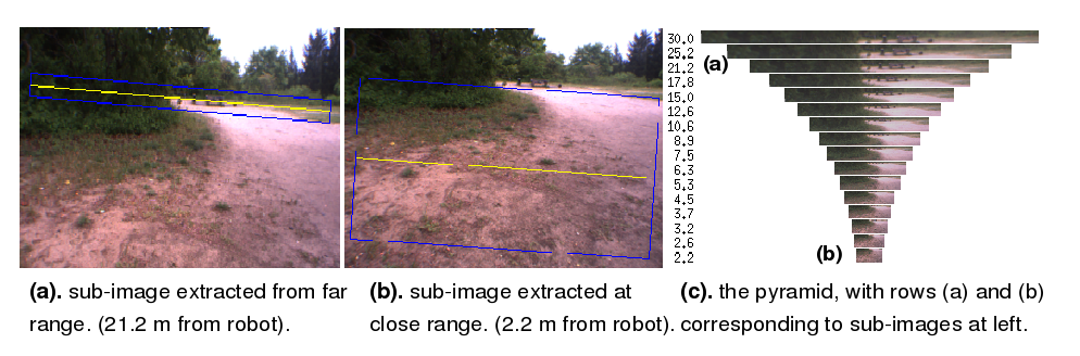
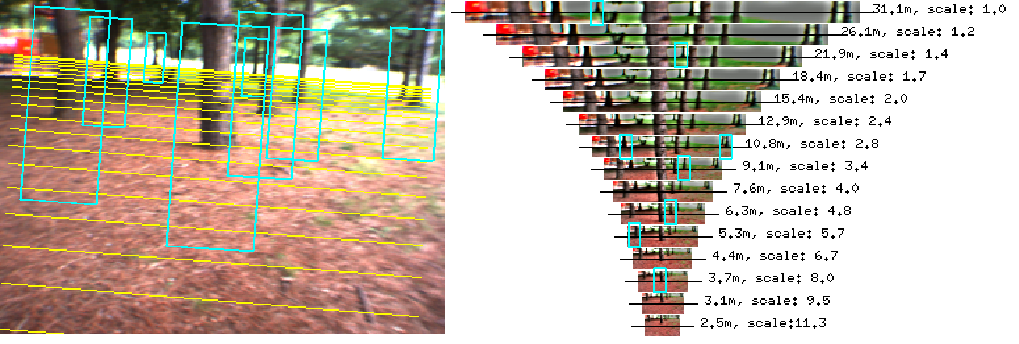
More precisely, an pyramid of distance-normalized bands is
built. Each band is parallel to the horizon, and contains
the feet of obstacles at a given distance from the robot.
Each extracted band is then resized to make it a uniform height (12
pixels), resulting in image bands in which the appearance of an object
on the ground is independent of its distance from the camera (only the
band in which it appears varies). These uniform-height, variable-width
bands form a size-normalized image pyramid whose 20 scales are
separated by a factor of 2^(1/4). In order to trace the virtual lines
on the ground on which the bands are centered, a ground plane is
fitted to the stereo point cloud using a Hough transform.
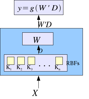
The image bands from the pyramid are fed to a 2-layer classifier
whose first layer is a series of 120 radial basis functions
trained with K-means (unsupervised), and whose second layer
is a linear classifier trained online as the robot runs.
The last layer of the convolutional net is trained on-line while the
robot is running. It is trained on nearby bands (up to 10-12 meters)
using labels provided by stereo vision, and is then applied to all the
bands, including the ones that are outside of stereo range (up to
30-35 meters).
The classifier properly generalizes to far away bands since
the objects in the distance-normalized bands appear with the
same size regardless of their distance.
By classifying windows taken from the bands of the image pyramid,
traversibility information can be directly mapped to specific world
coordinates, since the distance to the center of each band is
known. Thus, the pyramid provides the structure so that the long-range
obstacle detector (OD) can generate accurate range maps.
The long-range OD goes through a labeling, training, and
classification cycle on every frame. First, each overlapping 12x3
pixel RGB window from the right camera is assigned a traversibility
label (ground or obstacle) if it is within stereo range (less than 10
meters) and if stereo data is available. Then feature vectors are
computed for all windows over the entire pyramid. Each feature vector
is comprised of euclidean distances or correlations between a 12x3 RGB
window and 100 fixed prototypes trained in advance with an
unsupervised learning algorithm. A logistic regression classifier is
applied to the feature vectors, and trained using the labels provided
by stereo. The resulting classifier is then applied to all feature
vectors in the pyramid, including those with stereo labels.
The picture below shows examples of the maps generated by the
long-range obstacle detector. The long-range OD not only yields
surprisingly accurate traversibility information at distance up to 30
meters (far beyond stereo range), but also produces smooth, dense
traversibility maps for areas that are within stereo range. The
stereo-derived maps often have noisy spots or holes - disastrous to a
path planner - but the adaptive long-range OD produces maps that are
smooth and accurate, without holes or noise.
NSNYU System v1.0: Building a Polar Map from Stereo
Version 1.0 of the NSNYU system was operational from February 2006
to July 2006.
This system drives significantly faster than the LAGR baseline
system (by a factor of 2.5), and was the fastest of all
the LAGR contestants as of March 2006.
Our first system, while conventional in its use of stereo, attempts to
solve the short-sightedness problem by separating the "tactical"
aspect of driving and avoiding obstacles from the "strategic" aspect
of map building and path planning. The basic design philosophy is
to trust our eyes more than we trust our map.
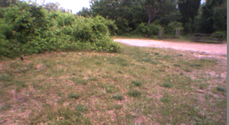
Picking good candidate directions in which to drive must be done
by looking around, not by looking at a map, and can be done without
good distance estimates. Consider the image on the right,
generating candidate directions can clearly be done, even though the
absolute distance of the various obstacles may be unknown. It's enough
to see that the right edge of the bush is straight ahead to figure out
we should veer right.
The distance of the obstacles may be unknown,
but the direction to take is obvious.
The main idea is to use stereo to build a local map of the
visible environment in polar coordinates. The polar
representation allows to represent angles (directions) with high
accuracy (independently of distance), while increasing the surface
area of map cells with distance, avoiding the problem created
by empty map cells at large distances.
Once candidate directions are generated in the polar map, picking the
best candidate can be done using traditional path planning on a map,
starting from each of the candidate points.
System Architecture. Tactical driving decisions a
performed in a 15-meter radius map in polar coordinates of the visible
environment. This process runs at roughly 6 frames per second.
Candidate waypoints from that local planning are sent to a global
planner in a long-range cartesian map. The local planning finds
candidates that are as close a possible to the current global
route.
Our system is therefore based on the following steps:
building a point cloud by running a stereo disparity
algorithm on both camera pairs. Stereo is run at 320x240
to maintain reasonable frame rate.
finding the ground plane using a robust plane fitting
algorithm on the point clouds (we got this idea from our
friend Dan Lee at U. Penn).
building a traversibility map of the visible area
in polar coordinate to a range of 15 meters by measuring
the density of points that are above the ground plane in each
map cell. Some postprocessing is also performed
(e.g. obstacle thickening).
finding a number of candidate waypoints within this polar
map using various heuristics. For example, waypoints are chosen
near the left or right edges of visible obstacles.
selecting which waypoint to drive to by running a path planning
algorithm (dubbed "Raystar") in the global map, using each candidate
waypoint as a starting point.
writing the local map in the a cartesian global map with
20cm resolution.
Ground plane fitting. The ground plane is found by a
robust fit of the point cloud obtained from stereo. Each yellow line
on the right represents an imaginary line on the ground at a given
distance from the camera. Point above the ground plane are colored
red, and points on the ground plane are colored green.
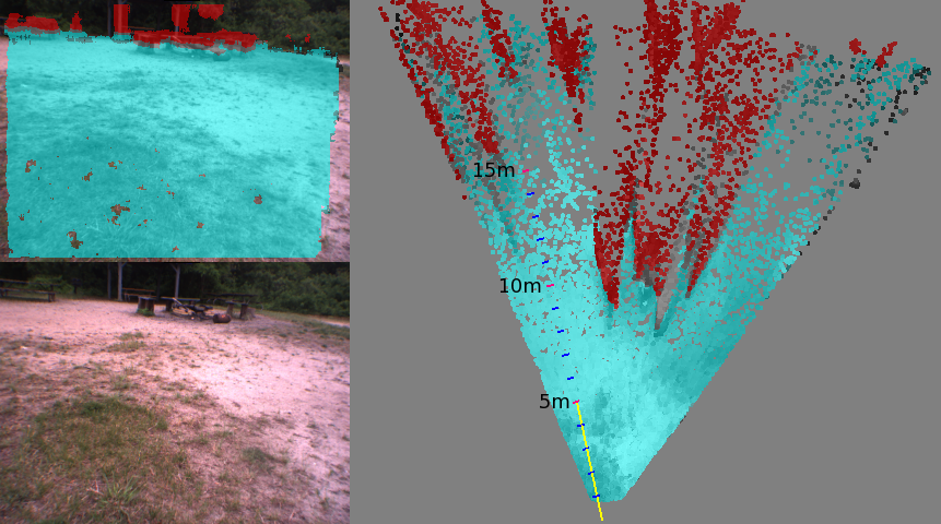
Traversability Map. Once the ground plane is found,
obstacles that are out of the groundplane (shown on red) can be
discriminated from points near the ground plane
(shown in turquoise). Click on the image for a larger view.
The practical range of simple stereo-based map building is limited for
two reasons:
1 it is difficult to estimate whether far-away points
are near the ground or above the ground;
2 the distance estimates are quite inaccurate for points more
than 7 or 8 meters away from the camera.
To solve problem 1, we estimate the parameters of the ground
plane by fitting a plane through the stereo point cloud. Two methods
were used: Hough transform on point clouds in elevation, azimuth,
disparity space; and EM-like robust plane fitting on point clouds in
XYZ space. The traversibility of an area is estimated by measuring
the density of points that are above the ground plane in that
area.
Problem 2 is approached by noting that, while absolute range
estimates of distant points are inaccurate, relative range estimates
are relatively accurate, and azimuth estimates are very accurate.
This suggests that searching for good direction in which to drive the
robot is better performed using a map of the visible environment
represented in polar coordinates, rather than using a cartesian
map of the entire ground. Our system identifies candidate waypoints up
to 15 meters away in this local polar map, and uses them as starting
points of a path finding algorithm in a global cartesian map.
An example of a 15-meter range stereo map is shown at right.
The candidate waypoints are shown as hollow circles. Candidate waypoints
are generated using a ray-casting algorithm followed by various
selection heuristics. For example, candidate waypoints are generated
near edges of obstacles.
Once candidate waypoint have been generated, a path-finding algorithm
is run in the global map starting from each candidate waypoint.
Given the current global map, the path finding algorithm finds the
approximate shortest path from each condidate waypoint to the goal.
The candidate waypoint with the shortest associated path to the goal
is chosen.
Since the path-finding algorithm can take a long time to compute a
path, it is run as a separate process. While the path is being
updated, a fast-looping "autopilot" algorithm is used to steer the
robot towards the candidate waypoint that is closest to the
latest best path.
Example of polar map with candidate waypoints.
The map has a range of 15 meters
Path Finding with Raystar
The path finding algorithm is a novel approximate algorithm
based on ray casting, dubbed ``Raystar''.
The algorithm is built around the classical A* algorithm, except that
candidate waypoints are generated from the current waypoints by
casting rays at a predetermined distance. If a ray hits an obstacle,
no candidate waypoint is generated on that ray. Various heuristics
are used to place waypoints on rays. Those candidate waypoints are
place on the A* "open list".
While the algorithm is suboptimal, it is considerably faster than
traditional A*, in which new candidate waypoints are immediate
neighboring cells of the current waypoints.
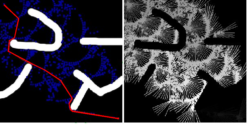
Example of run of the "raystar" path-planning algorithm
on a synthetic map (click in image for larger version).
Example map building and path planning produced
by the system on a real run (click in image for larger version).
Software Architecture
The LAGR robot contains three 1.4GHz Pentium M computers with flash
drives (and no hard drive) running Linux. A fourth computer, which is
not accessible to high-level software, takes care of low-level tasks
(reading the sensors and preprocessing the signals, interacting with
the radio control, and sending commands to the motors). The computers
are connected through a Gigabit ethernet network and can talk to the
outside world throug a WiFi bridge.
The first computers, called lagr-lefteye, is connected to the left
stereo camera pair. The second one, called lagr-righteye to the right
camera pair, and the third, lagr-planner is for general use.
Our software is entirely implemented in the Lush language. Lush is an
object-oriented dialect of Lisp with numerous libraries for numerical
computing, image processing, computer vision, machine learning. Lush
has two main advantages for this project:
The Lush compiler can generate very efficient code for numerical
functions.
It is extremely easy to integrate C/C++ code with Lush code. In
fact, it is even possible to mix C/C++ code with Lush code within
a single Lush function.
This allowed us to use interpreted Lush code for all the high-level
processing, compiled Lush code for complex mid-level functions, C/C++
code for all the low-level numerical operations, and highly optimized
library functions called from Lush for all the heavily repetitive
numerical operations, such as low-level image processing and
matrix function. We made heavy usage of the Intel Performance
Library for this.
The system runs four Lush processes that communicate through Lush's
"remote-lush" class. This mechanism allows two Lush processes to
communicate data structures through Lush's built-in data
serialization protocol. It also allows one Lush process to request
the evaluation of a Lush expression by another Lush process
(with blocking or non-blocking synchronization).
The main Lush process runs on the lagr-planner computer. Its main loop
runs at an average of about 20Hz. Given the current best path to the
goal and the current candidate waypoints, it picks the candidate
waypoint that is closest to the best path, and steers the robot
towards it, adjusting the speed if necessary. The speed is adjusted as
a function of the curvature of the trajectory and the estimated
distance to the neareast obstacle.
The main process controls Lush processes running on each eye computer.
It sends them requests to compute the portion of the local map
that falls within their field of view. Whenever the eye computers
complete the processing of one frame, the main process integrates the
to half maps coming from the two eye computers, builds the composite
local map in polar representation, and computes the candidate
waypoints. The process on each eye computer runs at about 7 frames per
second.
The main process also sends requests to a fourth Lush process, running
on the lagr-planner computer, to compute the best path to the goal,
given the current set of candidate waypoints (using the "raystar"
algorithm). The time taken by this path-finding process is highly
variable. It depends on the size and complexity of the global map and
can vary between 0.1 second and 5 seconds.
In addition, the main process also detects wheel slips and bumper
hits. If a bumper hit or a long wheel slip is detected, the robot
enters an obstacle avoidance behavior. It puts a lethal obstacle in
its maps at the location of the hit, and backs up on its tracks for a
given distance. It then recomputes candidate waypoints.
In addition to all this, a lightweight thread writes diagnostic
information to a ramdisk file that is read by a display software
running on a remote laptop computer while the robot is running.
Excessive latency in the vision control loop can lead to catastrophic
behavior patterns, such as running into obstacles at high speed, or
oscillating wildly around the prescribed driving direction. Therefore,
the fast frame rate of video processing, and the quick update of the
driving direction by the main process are key to the overall
performance of the system. This is one of the reasons why we chose
to run the stereo at relatively low resolution (320x240) compared to
the maximum resolution of the cameras (1024x768).
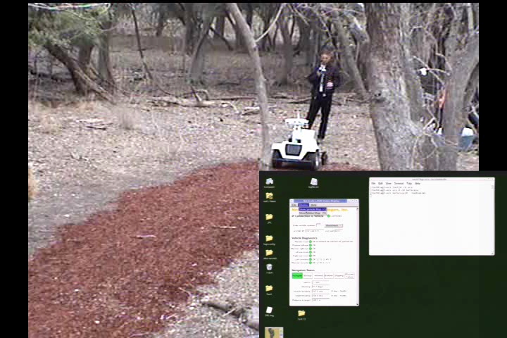
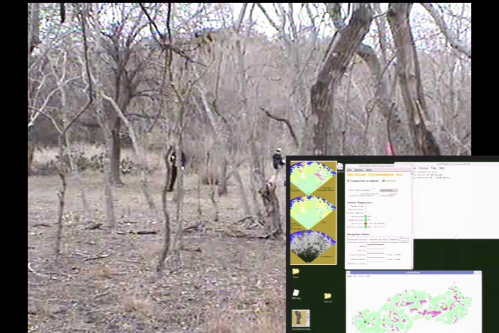
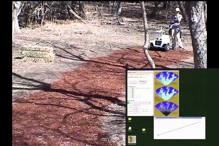
Videos of NSNYU System v1.0 on Test Courses
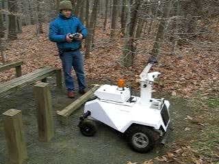
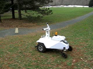
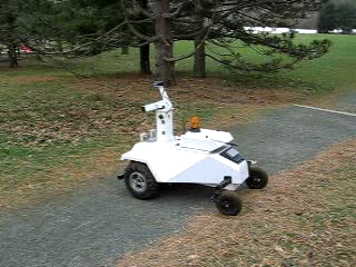
These videos show the robot running along various courses autonomously.
It is being controled by the v1.0 System, which uses stereo vision
to build a 15-meter range polar map. No learning is involved here,
beyond remembering the map from run to run.
This is faster than the LAGR Baseline System by a factor of 2 to 4.
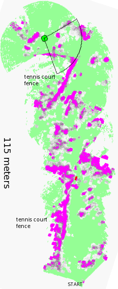
finding its way between rows of trees (Sandy Hook Park, NJ, 02/2006)
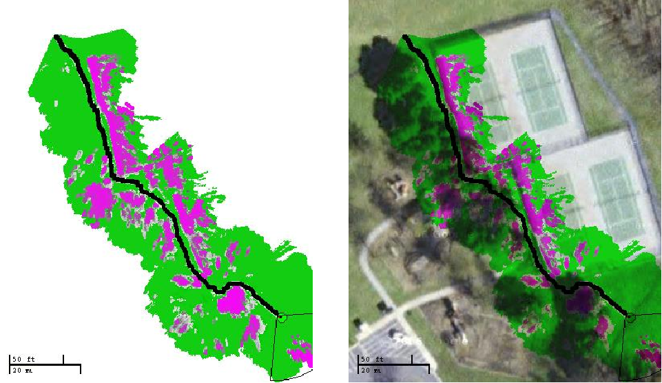
example of map generated as the robot drives
around the park near the tennis courts.
Videos of NSNYU System v1.0 during the Official LAGR Test 11
These videos shows the three official runs of the robot running the
record-breaking NYU/Net-Scale software during the LAGR Test 11
campaign in Feb 2006.
Run 1. Time: 5:10. The robot took the "shortcut" on the
right and wasted time in the cul-de-sac. At one point, the circuit
breakers of the motors tripped and had to be reset.
Run 2. Time: 2:55. Remembering the map from the previous
run, the robot takes the mulch path. Wheel slips towards the end
were interpreted by the robot as caused by hard obstacle hits.
This caused the robot to back up and waste a bit of time.
/td>
Run 3. Time: 2:29. The software decided to erase its map
because the GPS fix had drifted too much. The robot took the
"shortcut" again. It fell into the cul-de-sac but got out of it
quite quickly. This was the fastest run among all the teams for Test 11.
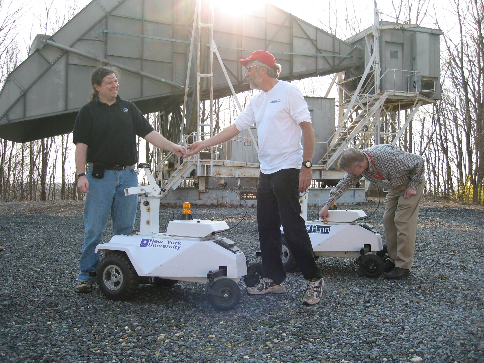
On March 31 2006, an informal race was organized between the
Net-Scale/NYU team and the U. Penn team.
The race took place on the grounds of the Crawford Hill Bell Labs
location, near the radio-telescope antenna used by Wilson and Penzias
to discover the background cosmic radiation.
Pictures
(click on pictures for larger versions).
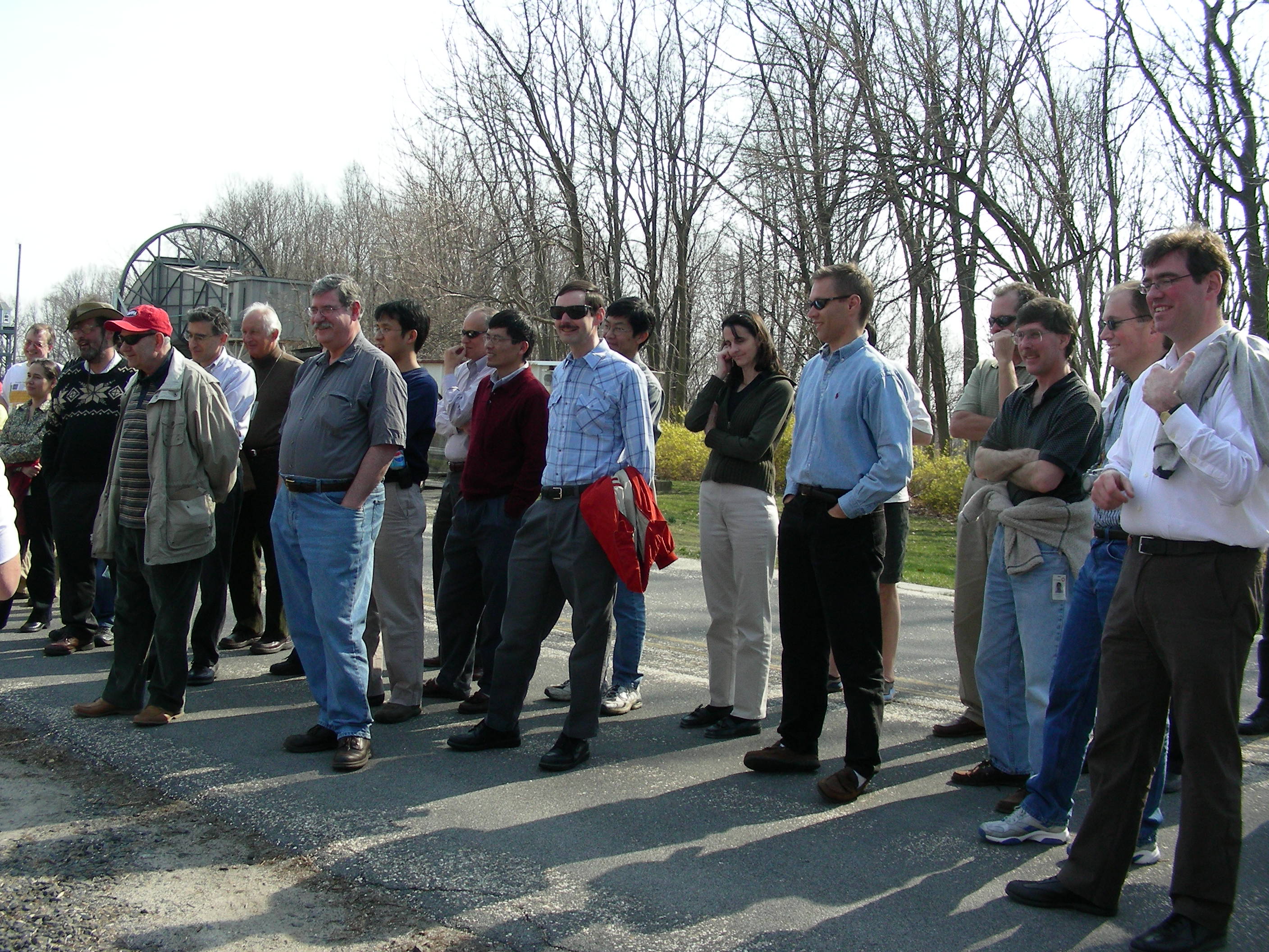
Some distinguished members of the cheering audience.
Many are current and former AT&T Labs and Bell Labs scientists
who wouldn't miss an afternoon of uber-geeky fun.
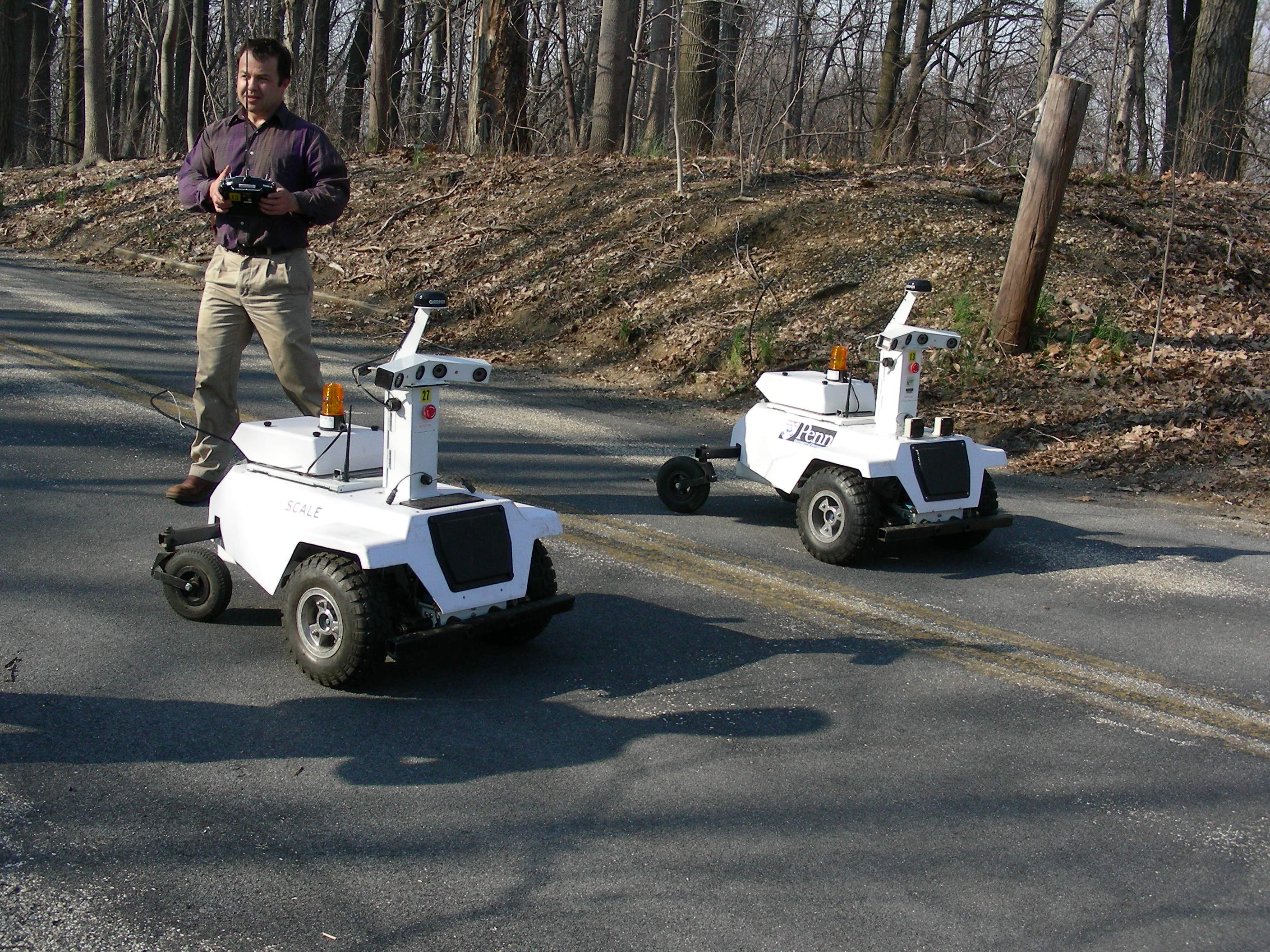
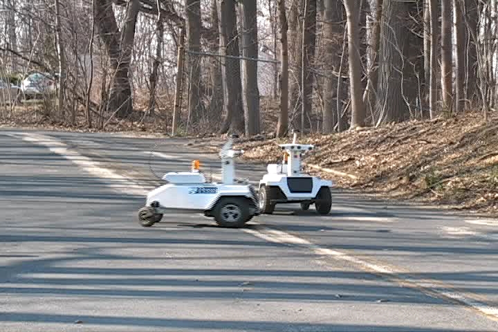
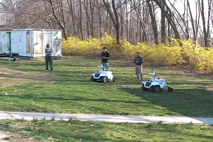
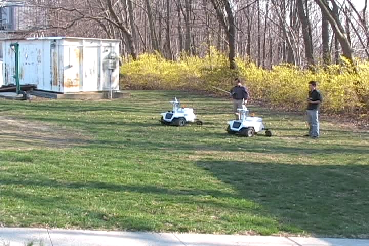
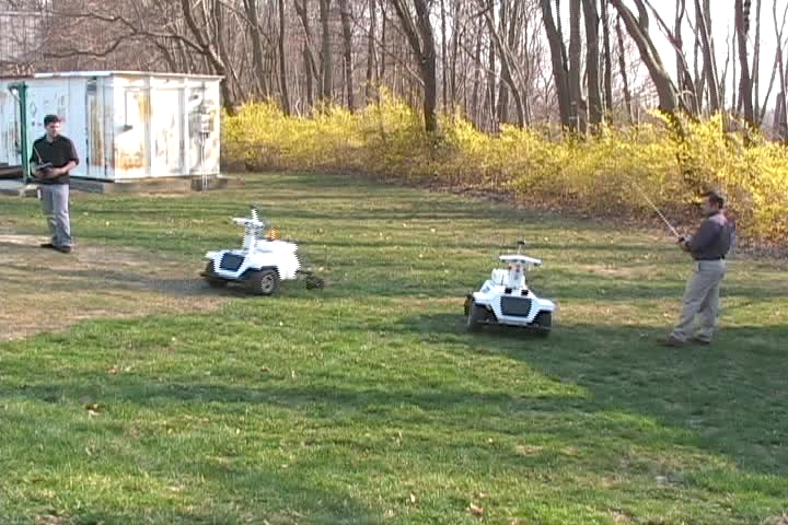
The two robots on the starting line. NYU/Net-Scale on the
left, U. Penn on the right. Jan Ben from the NS/NYU team holds
the transmitter, ready to switch his robot to autonomous mode
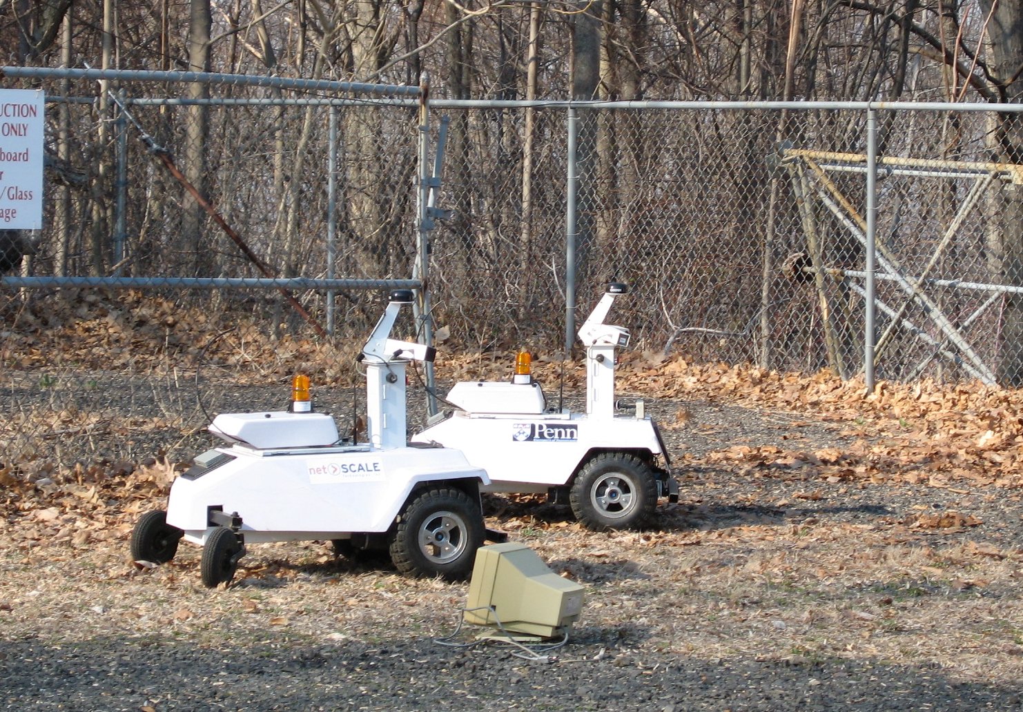
The robots are neck-to-neck during most of Heat 1.
U. Penn is slightly ahead, and will exit the fenced area
ahead of NS/NYU.
Videos
The judge with the red hat near the finish line is Vladimir Vapnik.
Heat 1. U. Penn wins: U. Penn pulls ahead and blocks the
passage to the NYU/NS robot. U. Penn pulls out of the cul-de-sac in
the fenced area ahead of NS/NYU and wins the heat.
[MPG] (30.6MB)
another shot of the same heat (lower quality):
[AVI] (19.3MB)
Heat 2. NS/NYU wins: NS/NYU is off to a great start and easily wins the heat.
Heat 3. NS/NYU wins: In a slightly easier course, NS/NYU
pulls ahead at the beginning. U. Penn takes a wrong turn and gets
snagged in front of the fence area.
Heat 4. U.Penn wins: NS/NYU is off to a good start and pulls ahead
quickly while U. Penn slowly finds its way through the first row of
obtacles. Unexpectedly, NS/NYU goes to the back of the fence area
and traps itself in a mound of dead leaves, spinning it wheel
hopelessly. U. Penn joins it briefly, but eventually frees itself
from the leaves and wins the heat, while NS/NYU still
digs its wheels deeper and deeper into the leaves.
After a close race, NS/NYU wins over U. Penn 3 to 2.
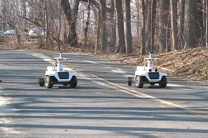
The two robots in front of the Big Bang Antenna.
Yann LeCun (left) receives the winner's trophy
from the DARPA/LAGR program manager Larry Jackel
(wearing the red hat)
The NS/NYU robot wears permanent scars of the
fierce battle with its rival from Philadelphia.
More Pictures
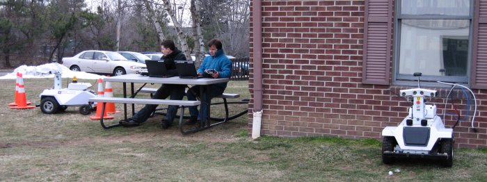
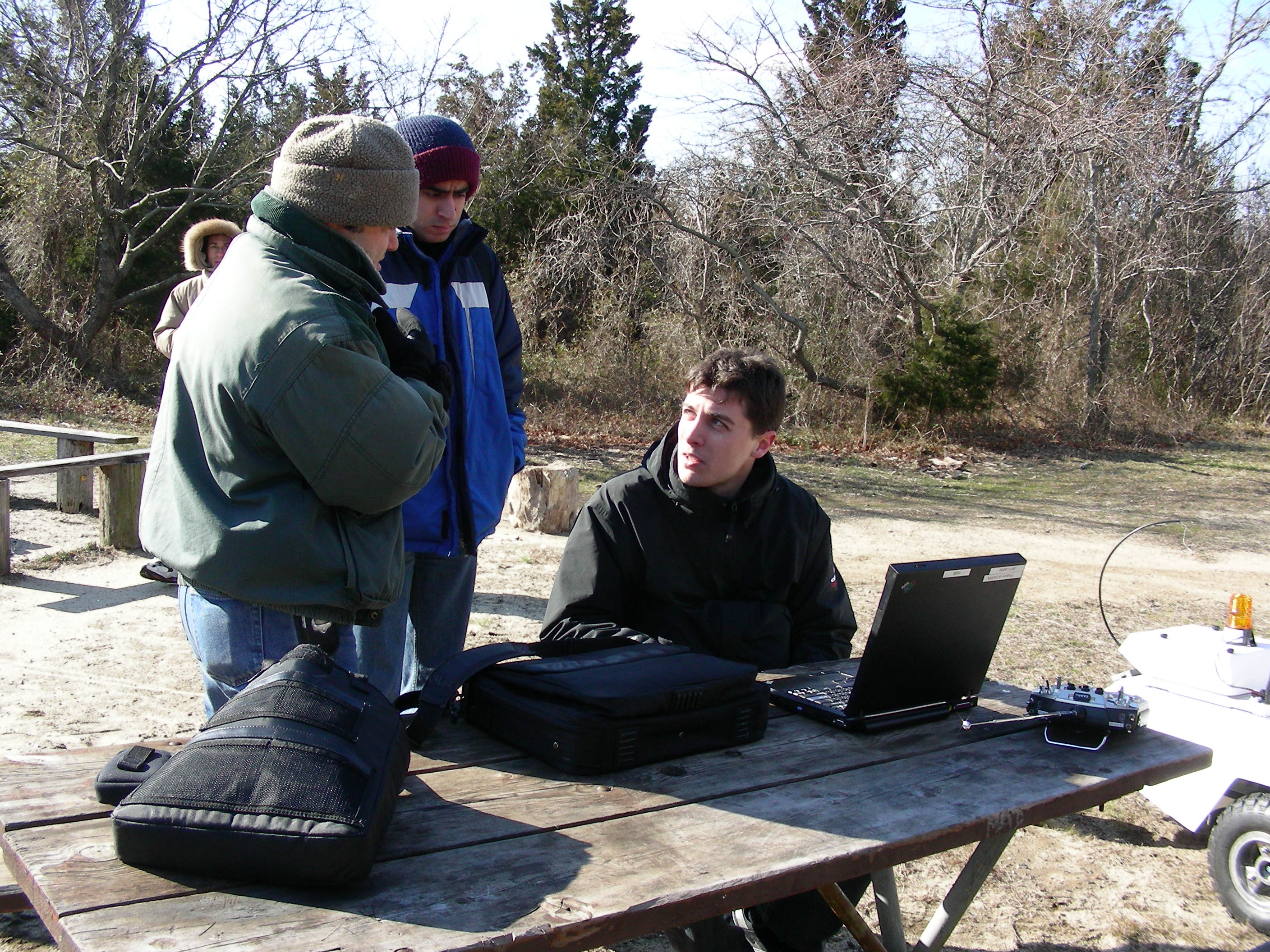
The Joy of Field Robotics in Winter
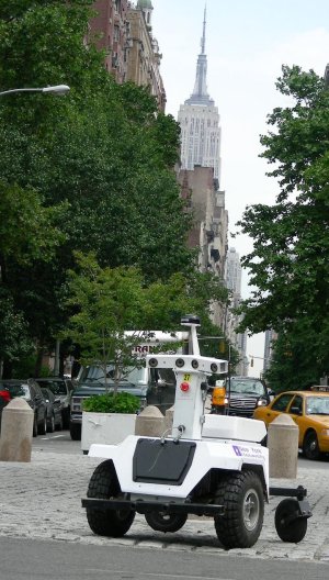
LAGR in New York City
Pictures are video clips are available
here,
and here.